[Author’s Note: This series of articles predates my joining the AV industry. It may have some inaccuracies, but I am leaving it up in case it helps people]
In part 1 of this article we introduced the autonomous vehicle functional safety standard, ISO 26262. We discussed its similarities and differences with IEC 61511. The first post covered parts 1-4 of ISO 26262, which covers the vocabulary, general requirements, conceptual design, and the system-level design. After your vocabulary lesson, you could be forgiven for exclaiming: “These standards are so dry! You’re killing me!” (to paraphrase a famous autonomous vehicle maker).
In today’s post, we will dedicate the entire post to covering part 5 of ISO 26262, which covers product development at the hardware level. This section gets into the “meat” of what is ASIL and how is it determined. This part is where ISO 26262 differs the most from IEC 61511. As we will see below, some of these differences are just terminology, while others are more fundamental.
Looking ahead, we will have a final part 3 to this article that will cover parts 6-10 of ISO 26262. I hope you are enjoying the posts, because I am darn well going to finish them whether you like it or not! 😉 Seriously, after studying the automotive standard, I am fascinated by both the similarities and the differences from process industry practices. The process industries have a 20-year head start in functional safety, but I think we can both learn from and teach the automotive industry a thing or two about functional safety.
Hardware Design
Part 5 of the standard is dedicated to the development of the hardware required to achieve safety goals (software is covered in the next part). In this part, the technical safety requirements developed in Part 4 are allocated to specific hardware and software designs. This could be thought of as equivalent to detailed engineering in a typical IEC 61511 project.
Without going too deep into the details, the ISO standard requires that the design consider several factors, including:
- Response to failures, including transient faults
- Diagnostic capabilities
- Consideration of fault detection times
- Expected failure rates of components
- Design verification requirements
- Consistency with the higher-level safety specifications
The hardware detailed design is captured in three main deliverables
- Hardware Safety Requirements Specification
- Hardware-software Interface Specification
- Hardware Safety Requirements Verification Report
The ISO standard does not go into great detail on the hardware design process (neither does IEC 61511), so I will not either.
The later sections of Part 5 discuss the quantitative verification of the hardware via various metrics (including ASIL), which is where the rest of this article will focus.
Fault Metrics
Clause 8 covers the evaluation of the hardware architectural metrics. Specifically, these metrics are intended to evaluate the effectiveness of the hardware architecture in dealing with random failures. This is distinct from the evaluation of random hardware failures (i.e. ASIL) covered in Clause 9.
Diagnostic coverage is defined much the same way as it is in the IEC standards. Diagnostic coverage is required to be estimated based on failure rates from recognized industry source, statistics based on field returns or tests, expert judgement.
The two metrics defined in this part are:
- Single-point Fault Metric – measures the robustness of the design to single-point and residual faults. Higher is better.
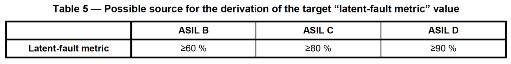
- Latent-fault Metric – measures the robustness of the design to latent faults. Higher is better.
As with many of the ISO requirements, these metrics only apply to higher ASIL function (i.e. B, C, or D).
Before discussing the metrics, it is useful to remember the taxonomy of faults/failures (from Part 1) used by ISO 26262, which is different from IEC. The total failure rate λ can be broken down into:
λ = λSPF + λRF + λMPF + λS
where:
λSPF: Single Point Faults (i.e. a DU fault where there are no diagnostics)
λRF: Residual Faults (i.e. a DU fault not covered by diagnostics)
λMPF: Multiple Point Faults (i.e. a combination of independent SPFs)
λS: Safe Faults
Single-point Fault Metric
The single-point fault metric is defined as the sum of the multiple-point faults and the safe faults divided by the total failure rate, i.e. the following ratio: Σ(λMPF + λS) / Σ(λ)
Note: The name “single-point fault metric may initially be confusing, since the single point fault rate (λSPF) does not appear in the formula! However, the formula can equivalently be written as: 1- Σ(λSPF + λRF) / Σ(λ)
This ratio looks suspiciously like the IEC 61508 concept of Safe Failure Fraction (SFF), with the notable exception that multiple-point faults are also considered “safe”. The inclusion of multiple-point faults is a somewhat unusual approach, but it is probably why the latent-fault metric is also calculated.
A quantitative target for the single-point fault metric is set by the standard based on the ASIL target:
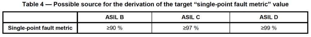
By combining safe faults and multiple-point faults into the same metric, this metric has a similar impact to the SFF-based hardware fault tolerance requirements in IEC 61508. In other words, if the single-point fault metric is to low, additional fault tolerance will convert those faults to multiple point faults and improve the metric. Sound familiar?
Latent Fault Metric
The latent fault metric is defined as the sum of the multiple-point faults that are perceived by the driver or detected by diagnostics plus the safe faults divided by the total multiple-point and safe faults, i.e. the following ratio: Σ(λMPF(Per/Det) +λS) /Σ(λMPF +λS).
Again, this concept looks very similar to the concept of IEC 61508 diagnostic coverage, except that it also includes the possibility of driver “perception” of and response to faults. This is generally not considered in IEC 61511 since most systems are dormant and activate on demand.
A quantitative target value for the latent-fault metric is set by the standard based on the ASIL target:
My interpretation of the two required fault metrics is that they are a sort of roll-up of several IEC concepts, including diagnostic coverage, safe failure fraction, and hardware fault tolerance. The end result should be that reasonable amounts of diagnostics and fault tolerance should be built into the system before the ASIL is even calculated. Of course, the SFF concept and the HFT requirements in the IEC standards are somewhat notorious for the “numbers games” they have inspired (e.g. see here and here). It would be interesting to see if the automotive industry is more successful in this regard.
Automotive Safety Integrity Level (ASIL)
Clause 9 finally introduces us to the Automotive Safety Integrity Level (ASIL) and how to evaluate it. Similar to the IEC 61511, the goal of the ASIL calculation is demonstrate that the probability of random failures is sufficiently low to meet the safety goal.
The ISO standard specifically states that the evaluation is limited to random hardware failures, neglecting systematic failures. As regular readers already know, I strongly disagree, and believe that systematic failures should be both qualitatively and quantitatively considered wherever possible.
Two options are given for calculating ASIL:
- Probabilistic Metric for random Hardware Failures (PMHF)
- Individual evaluation of faults (i.e. cut set analysis)
We will briefly discuss each approach below.
Probabilistic Metric for random Hardware Failures (PMHF)
This approach is similar to the IEC 61508 approach for a high demand or continuous SIF, where a target probability of failure per hour (PFH) is specified for each SIL level. The ASIL targets are shown below:
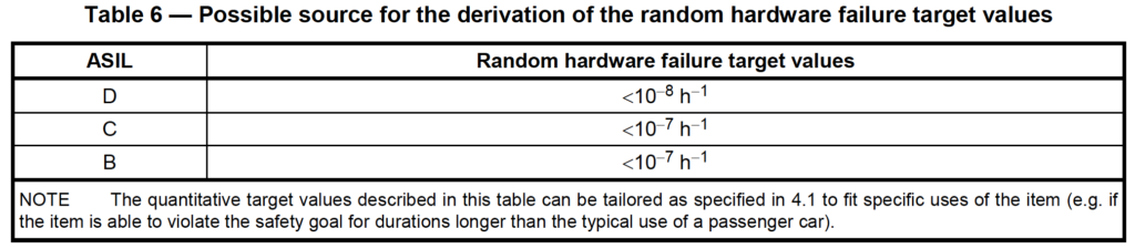
Note that for ASIL:
- No quantitative target or calculations are required for ASIL A
- The PFH targets for ASIL B and C are the same (other requirements differ)
- The PFH values for ASIL do not exactly match up with the targets for SIL. The ASIL targets are higher, i.e. ASIL B/C is equivalent to the PFH for SIL3. ASIL D is the equivalent of SIL4. (Although ASIL A does not have a quantitative target, presumably it is equivalent to SIL2 if the risk matrix is linear.)
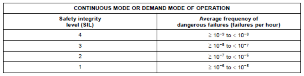
Since many of us don’t do high demand mode SIL calculations every day, the high demand SIL table from IEC 61508 is shown below for reference:
The probabilistic metric evaluation must be done quantitatively, although the standard does not specify the method. Quantitative fault tree analysis (FTA) is suggested as one method. It does have specific requirements that the analysis must cover, including the concept of “exposure duration” which is roughly equivalent to the MTTR considered in SIL calculations.
For higher ASIL C and D targets, the standard requires that a single-point fault in a hardware part shall only be considered acceptable if “dedicated measures” are taken, where dedicated measures are steps to ensure the failure rate is low, such as over-design, separation, sampling, etc. This concept is somewhat similar to the proven-in-use concepts of IEC 61508.
Individual evaluation of faults (i.e. cut set analysis)
The second option for evaluating ASIL is based on evaluating faults one at a time. A simple flowchart is provided in the standard to describe the iterative design process. The advantage of this approach appears to be that a complex model (e.g. FTA) of the entire system is not required for the analysis. I suspect (but have not confirmed) that the downside is that this approach is more conservative.
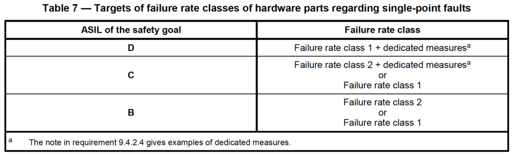
This method introduces the concept of failure rate class for individual hardware parts. The failure rate class ranking for a hardware part failure rate is determined as follows:
- Class 1 = <10-10 /hr
- Class 2 = <10-9 /hr
- Class 3 = <10-8 /hr
- etc. (where Class i = Class i-1 x 10)
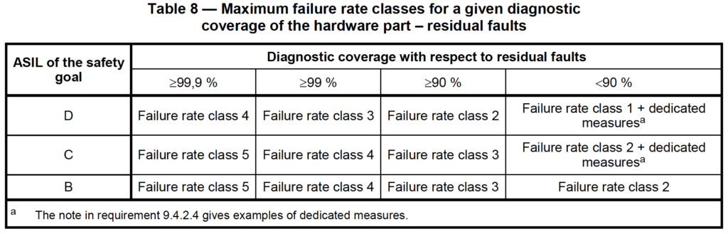
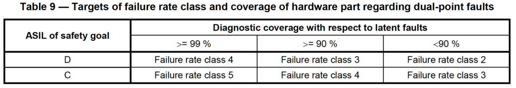
In this method, each ASIL level has one or more failure rate classes that are allowed to be used, as shown below. There is one table each for (i) single point faults (i.e. no diagnostics), (ii) residual faults, and (iii) dual point faults, as shown below:
This method of component “classes” is conceptually similar to the “parts counts” methods used in the past, most notably in MIL-HDBK-217. That itself is enough to make me skeptical of this approach since the military eventually shelved MIL-HDBK-217 for being wildly inaccurate.
I also wonder if the failure class targets in ISO 26262 are so conservative that this approach is infeasible. A Class 1 part as required for ASIL D must have a failure rate of less that 1E-10 /hr. Stated differently, the MTTF for that part must be more than 1,141,000 years. I want to know where to buy Class 1 devices for my SIFs! I suspect that this is a subtle way of encouraging hardware fault tolerance without strictly requiring it.
Wrap Up
Key takeaways from this part of the article include:
- The hardware design process is not specified in detailed in the ISO standard, but includes familiar concepts such as diagnostic coverage, failure rates, and verifications.
- The standard includes two fault metrics: (i) the single-point fault metric and (ii) the latent fault metric, which are similar to safe failure fraction (SFF) and diagnostic coverage (DC)
- The Automotive Safety Integrity Level (ASIL) is similar in concept to high demand SIL, but the levels are different.
- The standard gives two options for calculating ASIL, one based on an overall model of the function (similar to SIL calculations), and one based on consideration of individual faults.
In the final installment of this series, we will cover the highlights of parts 6-10 of the standard, most likely spending the most time on the informative part 10.
Thanks for reading! To ensure you don’t miss anything, please follow us on LinkedIn.
Great article